Making a smart power switch for my PC that doesn't support Wake-on-LAN.
I've been into Home Assistant for a while now, and something I've always wanted for my desktop PC was the ability to turn it on remotely. Unfortunately, my relatively expensive MSI X99S GAMING 7 motherboard does not support the most basic and fundamental feature called Wake-on-LAN, which would have made this trivial to achieve.
So I need some kind of external gadget to do this. There are some "out of the box" products that do this, even ones that use Zigbee, but they were in the range of $20-$30. Why pay that when an ESP32 is $4 and your time is worthless there's an opportunity to learn?
What we need
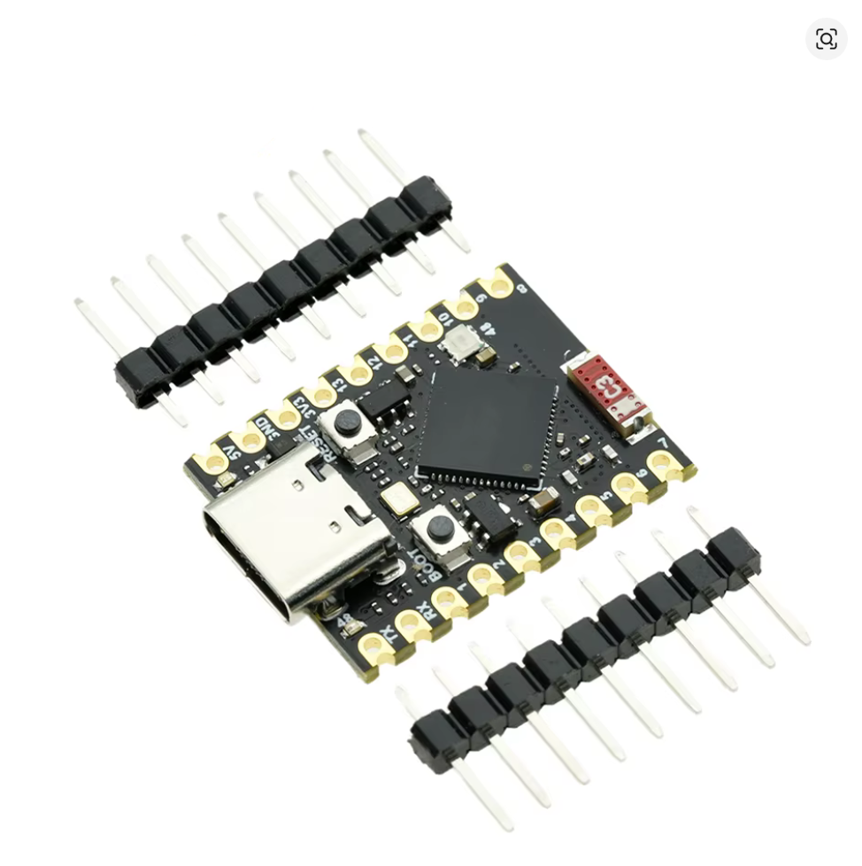
An ESP32
I have an ESP32-S3 "supermini" which is overkill for this, any ESP32 would work. 1
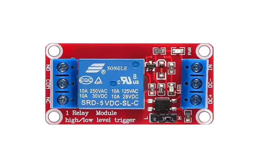
A 5V relay or equivalent
Here I'm using a relay module with a "SRD-5 VDC-SL-C" relay. This is also probably 100x overkill and a transistor would work, but it's what I was familiar with.
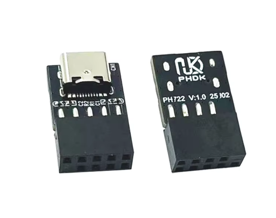
Something to power the ESP32
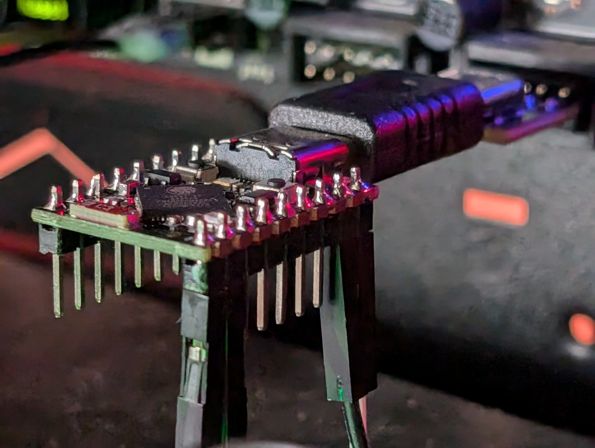
To power the ESP32, a USB 9 pin internal motherboard header to USB-C adapter (or equivalent for whatever your motherboard has) and a USB C Male to Male Adapter because the above adapter has the wrong gender for us to directly connect the ESP32. Funnily enough these are possibly not quite legal per USB-C spec. You can do something else here like use a USB cable or use the USB 3.0 motherboard headers, but I went with this approach because USB 2.0 is simple and this keeps the form factor small (or at least, it was supposed to).

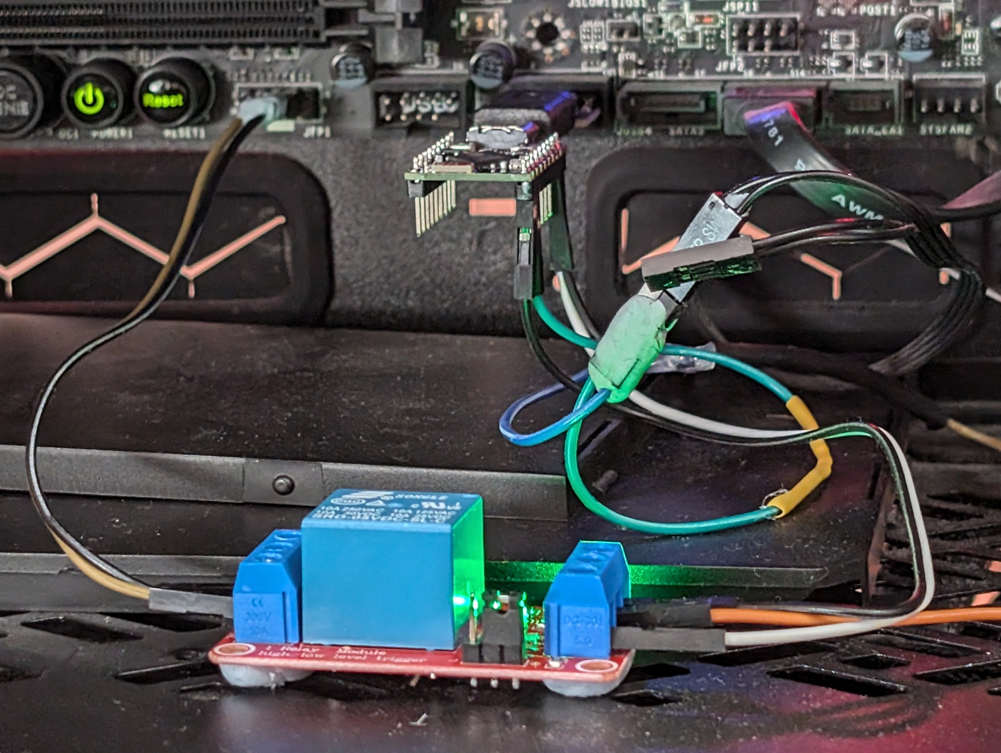
It looks a bit silly when they're all plugged in together:
Miscellaneous
- Some Dupont jumper cables because I was too lazy to make my own neat wiring
- Some Blu Tack to stick my resulting lazy wiring together (and prevent the relay from shorting on the metal case)
- The manual for the motherboard so we can figure out which of the pins on the front panel header we need
Setting it up
When I first started this, I (having only the bare minimum electronics knowledge to get by) had hoped that I could implement this without any additional modules or components other than the Dupont wires. I made a few mistakes like trying to make my own USB-C dongle, not realising that the front panel pins were 5V, then I realised I needed a relay, then I was trying with a relay that wasn't 5V, so it took me a few goes to land on a working setup.
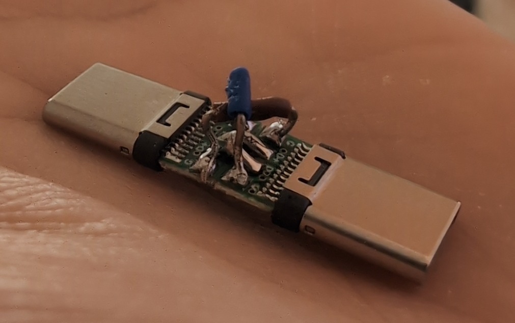
It would have worked if I had breakout boards with the CC pin but these are preconfigured with a resistor
When I went to wire up the relay, intuitively I thought that the motherboard's front panel ground power pin should be connected to "Normally Closed" (NC), and that "shorting" the connection would cause the PC to boot. When I first set this up, for some reason it just caused my PC to endlessly reboot. Huh? I then tried connecting it to the "Normally Open" (NO) terminal, which sort of worked, but I was still getting some strange behaviour. Conclusion? The relay, when set to activate on "HIGH", activates the "on" LED when NC is off.
From the store page:
Use High Level Trigger
When ¡°IN¡± input High Level Signal, the ¡°NO¡± connect with ¡±COM¡±
When ¡°IN¡± input Low Level Signal, the ¡°NC¡± connect with ¡°COM¡±
Or in other words, when the input is high, NC is disconnected from COM (but the LED is on). Kinda the opposite of what I expected.
Wiring
- Motherboard front panel power button ground pin to relay's NC terminal
- Motherboard front panel power button positive pin to relay's COM terminal
- ESP32 GPIO (in my case, GPIO8) to the relay's data pin
- We can power the relay from the 5V in pin on the ESP32. Don't forget to solder the jumper if you're using the S3 devkit!
- Because the supermini only has 1 ground pin, I needed to make a Y-cable to share ground between the relay and the physical power button on my case
- The positive pin on the case's physical power button goes to a GPIO pin (GPIO9) on the ESP32
ESPHome
I "programmed" the ESP32 with ESPHome, which is to say I didn't need to program much of anything at all. The key parts are:
# [Wi-Fi, board setup, API keys, etc. go here]

wifi:
  power_save_mode: NONE  # I think I may have damaged the antenna while setting this all up

binary_sensor:
  - platform: gpio
    id: my_power_button_input
    name: Physical Power Button
    internal: false  # technically we don't need this in Home Assistant, I've only hooked it up for debugging
    entity_category: DIAGNOSTIC  # hide it from the main dashboard as we only need it for debugging
    pin:
      number: GPIO9
      inverted: True  # so that the sensor shows as "on" when the button is physically pressed down
      mode:
        input: true
        pullup: true  # this is key to get the ESP32 to detect when the physical button is pressed
    on_press:
      then:
        - switch.turn_on: my_power_button_output_switch # relay the physical button changes to the... relay
    on_release:
      then:
        - switch.turn_off: my_power_button_output_switch

switch:
  - platform: gpio
    id: my_power_button_output_switch
    name: "PC Power"
    pin:
      number: GPIO8
      inverted: True # pulling high opens the connection, we want pulling high to short the connection
    restore_mode: ALWAYS_OFF  # just in case...
    internal: false
    entity_category: DIAGNOSTIC

# These are the actual entities I'd be using in Home Assistant
button:
  - platform: template
    id: my_power_button_short_press
    name: "PC Power"
    on_press:
      then:
        - switch.turn_on: my_power_button_output_switch
        - delay: 500ms
        - switch.turn_off: my_power_button_output_switch
  - platform: template
    id: my_power_button_long_press
    name: "PC Power Long Press"
    on_press:
      then:
        - switch.turn_on: my_power_button_output_switch
        - delay: 4100ms
        - switch.turn_off: my_power_button_output_switch
More motherboard problems
The last problem to get this working was changing a strangely named setting "Resume by USB Device" in the BIOS settings so that the USB ports were providing power even when the PC was "off".
Conclusion
A couple of mistakes meant the design ended up being not quite as compact as I wanted. I plan to spend more time learning basic electronics theory and PCB design so I can make something purpose fit, and probably have it end up cheaper too. If I could be bothered, a 3D printed case would be smart to protect against shorts. It would also be good to have some kind of status as to whether the PC was turned on or not, maybe one of the LED pins could help with this.
-
An ESP8266 would technically work too but they're quite resource constrainted on ESPHome and an ESP32 isn't really more expensive. ↩︎