A small (lol) project to re-use an ATX PSU to power a WS2812B LED strip.
Warning: none of this is a tutorial or advice, I have no idea what I'm doing.
This is the 4th WS2812B LED strip I have running at home. I think they're pretty cool; they're extremely bright and each LED is addressable so you can do some cool effects. But more than that, if you DIY - they're cheap. They're so cheap that I don't need to worry about whether blowing a few hundred dollars on fancy LED strips is really a smart investment. Instead, the BOM look something like this:
| Item | Price (AUD) |
|---|---|
| WS2812B LED strip (5m, 144 LEDs per meter) | $45 |
| 3D-printed enclosure (@ $20/kg of PETG) | ~$5 |
| HU-M28W ATX breakout | $3 |
| ESP32C3 Supermini | $2 |
| Spare ATX PSU I found lying around | $0 |
Comparing the LED density to photos of other commonly available LED strips at local stores, the cost per LED is probably in the ballpark of a magnitude cheaper.
And, we get all this for free:
- Driven by free open source software
- Wi-Fi connectivity
- Integrates with Home Assistant
- Extensible
- Doesn't sell your personal data
- Doesn't rely on internet-connected services
- Doesn't need a subscription
- Doesn't force you to install (yet another) proprietary app on your phone
Power Supply
Each individual WS2812B LED draws between 30-60 mA (source), and we have 5m*144/m = 720 LEDs, which comes out to ~20-40A current draw (or 100-200 watts).
I could (and have in the past) bought a PSU to support this, but it ends up roughly doubling the cost of the project (quality is somewhat important here so we don't burn everything down). But I have this 750 watt PSU lying around, which should be plenty
Wrong
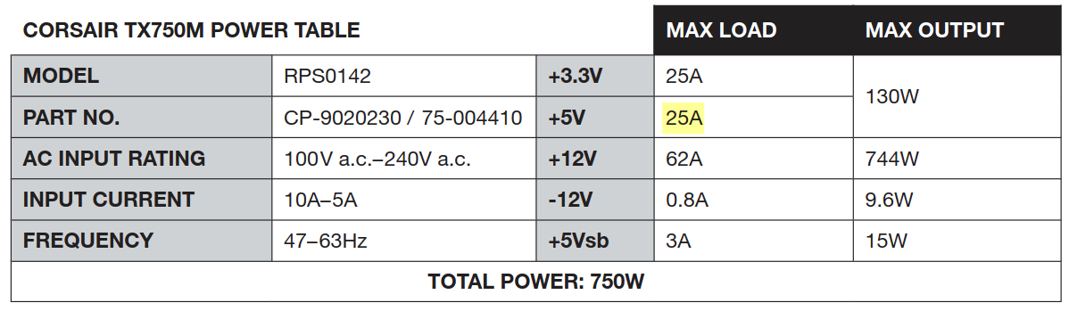
And out of the few I checked, this one is higher end in terms of 5V output.
Oops. Oh well, I wasn't going to run it at capacity anyway - lesson learned for next time. Maybe WS2811 (12V) would be more practical1.
Breakout
I've fiddled with PSU wiring before (using a paperclip to daisy chain power supplies to power auxiliary computer parts lol) and so I could've gone full DIY here but I don't have the appropriate connectors and spending a few dollars to save a bunch of headache seemed like a good idea:
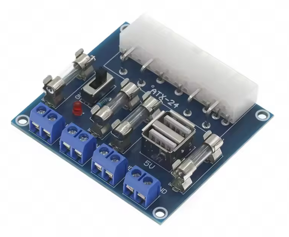
I think I added this to cart without fully considering what I was going to use it for, so only later did I realise that I may need to consider current ratings for it...
At least it has fuses? Which aren't specified in the product description, but some comments mention:
As delivered they are all 25a250v
It comes with 5A fuses
Err... Given I haven't heard any popping yet, I'm assuming the ones I got are 25A.
Update: yeah, the breakout runs uncomfortably warm when you up the brightness. I'd avoid using a breakout if I did something like this again, and just salvage or buy a socket for the 2x pin PSU cable.
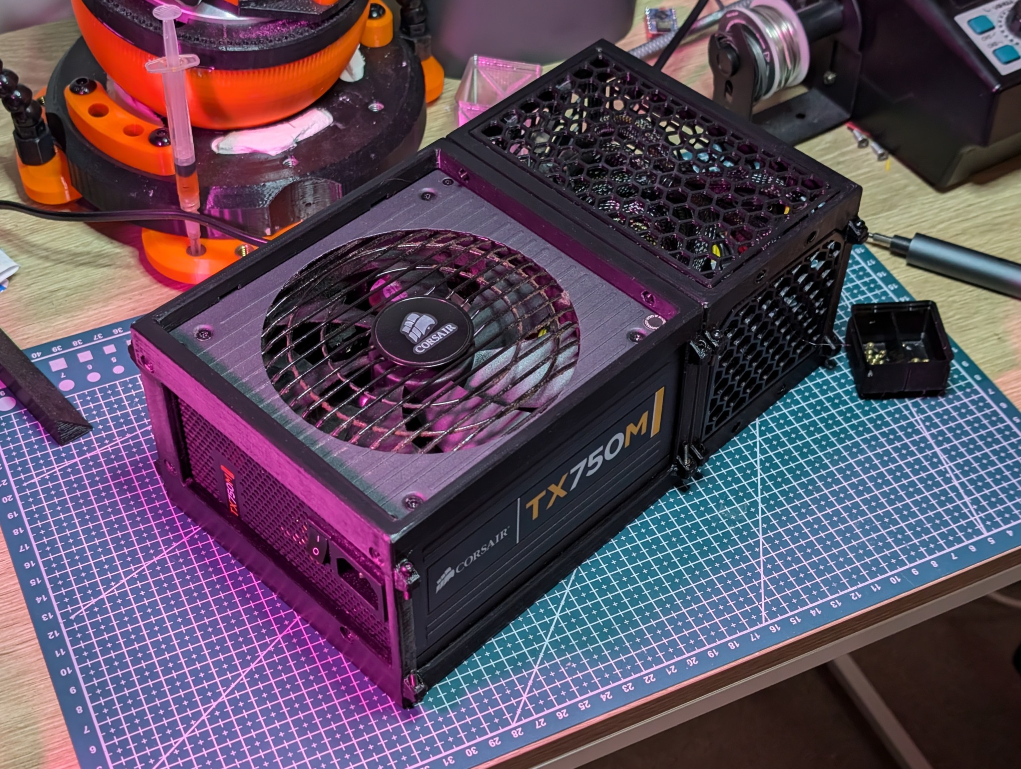
Enclosure
I wanted something to keep the PSU's (non-modular) cabling tidy, so I came up with the idea of creating a bit of a frame around the PSU and some panels to enclose it all:
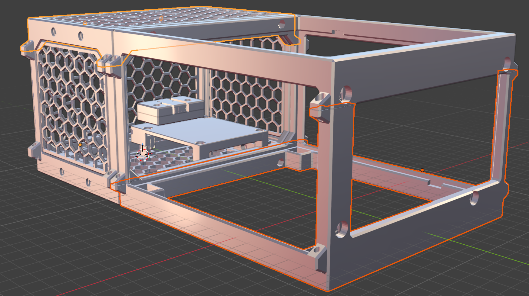
Lots of issues along the way:
- Printed the first iteration with the wrong kind of filament loaded (but the PSU didn't fit anyway, so probably lucky I wasted the cheap prototyping PLA)
- Realised I'd have to print a wasteful amount of supports to get the upper horizontal edges printed, forcing me to split each component in half
- To connect each half, I came up with the idea of these little trapezoids on the side, with one side containing a brass insert (which actually worked pretty well)
- Holes for the brass inserts weren't big enough, causing them to become clogged after installing
- One of the vertical edges snapped off. Luckily I hadn't bothered removing the trapezoids where they weren't necessary and I was able to use it to connect a vertical edge I printed by itself
- Forgot to include room for the PSU's 24-pin cable latch
- Top panel doesn't have screws, it's just held in place by the pressure from the PSU's cables trying to escape
- Eyeballed the capacity needed for all the excess cables, luckily it just fits, but the hex walls are kind of bulging out from the pressure
- The hex walls are really thin - on purpose, because they're mostly aesthetic, but it's not great how flimsy they are
- Mounting for the electronics ended up being far more complex than I desired (4 separate parts)
- Initially printed the ESP32C3 mount with no way to pass the wires through
- Tolerances for the walls were too tight; since they're joined together with screws, it would have been better to have made the gaps between parts too large rather than too small
- Didn't leave any fuel in the tank for designing any kind of interface to control it (buttons, switches) before I started to burn out on it
What was frustrating is that before starting on this enclosure, I actually had everything wired up, "programmed" and fully functional within 15-30 minutes of starting. Designing this took a good week's worth of spare time. I could probably benefit most from simplifying things here.
Anyway, I'm pretty satisfied with the finished product:
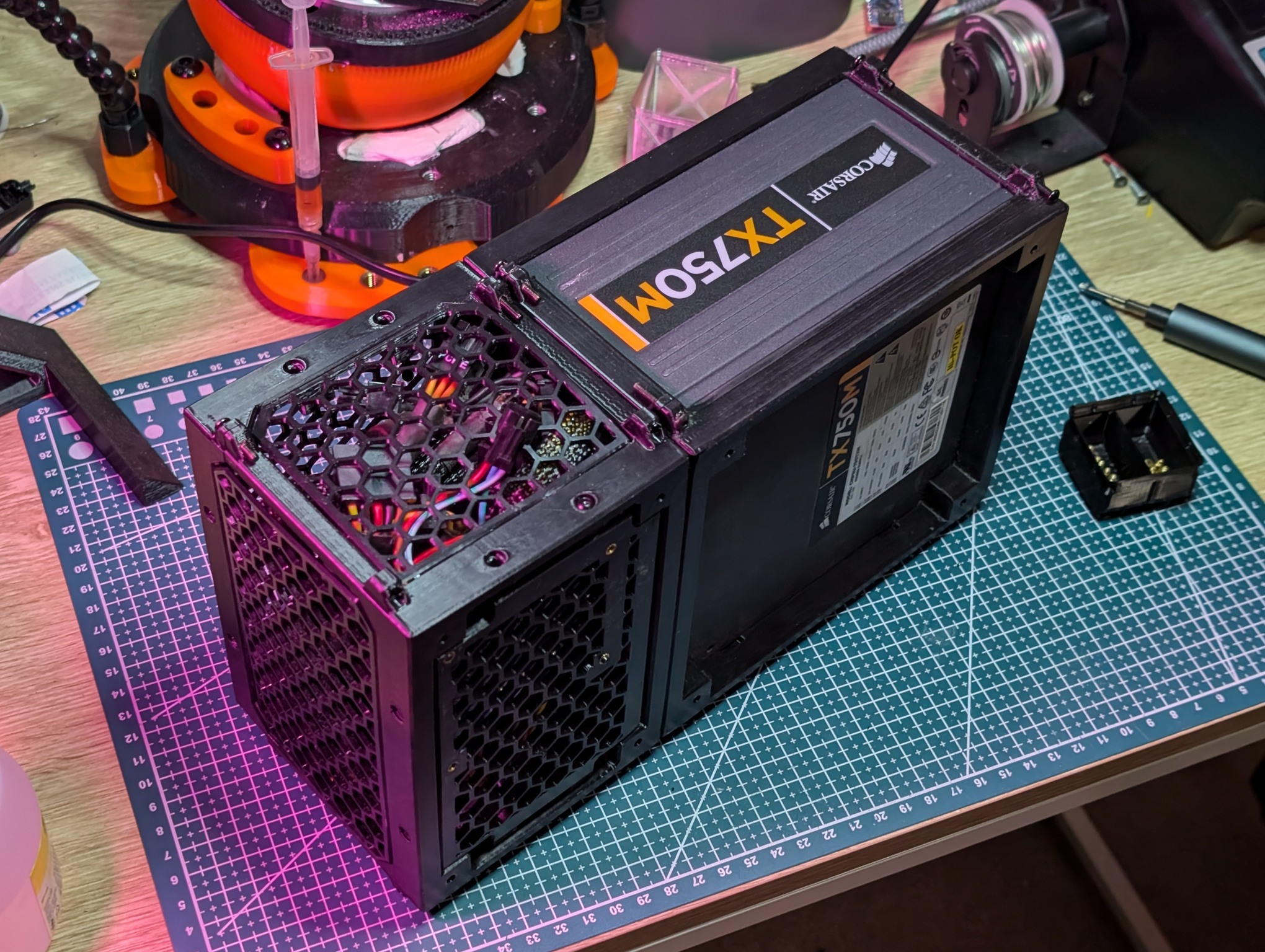
I almost forgot to add the additional power cable... There is no way you can safely run power through the 3 pin JST connector alone. Trust me, I've tried:
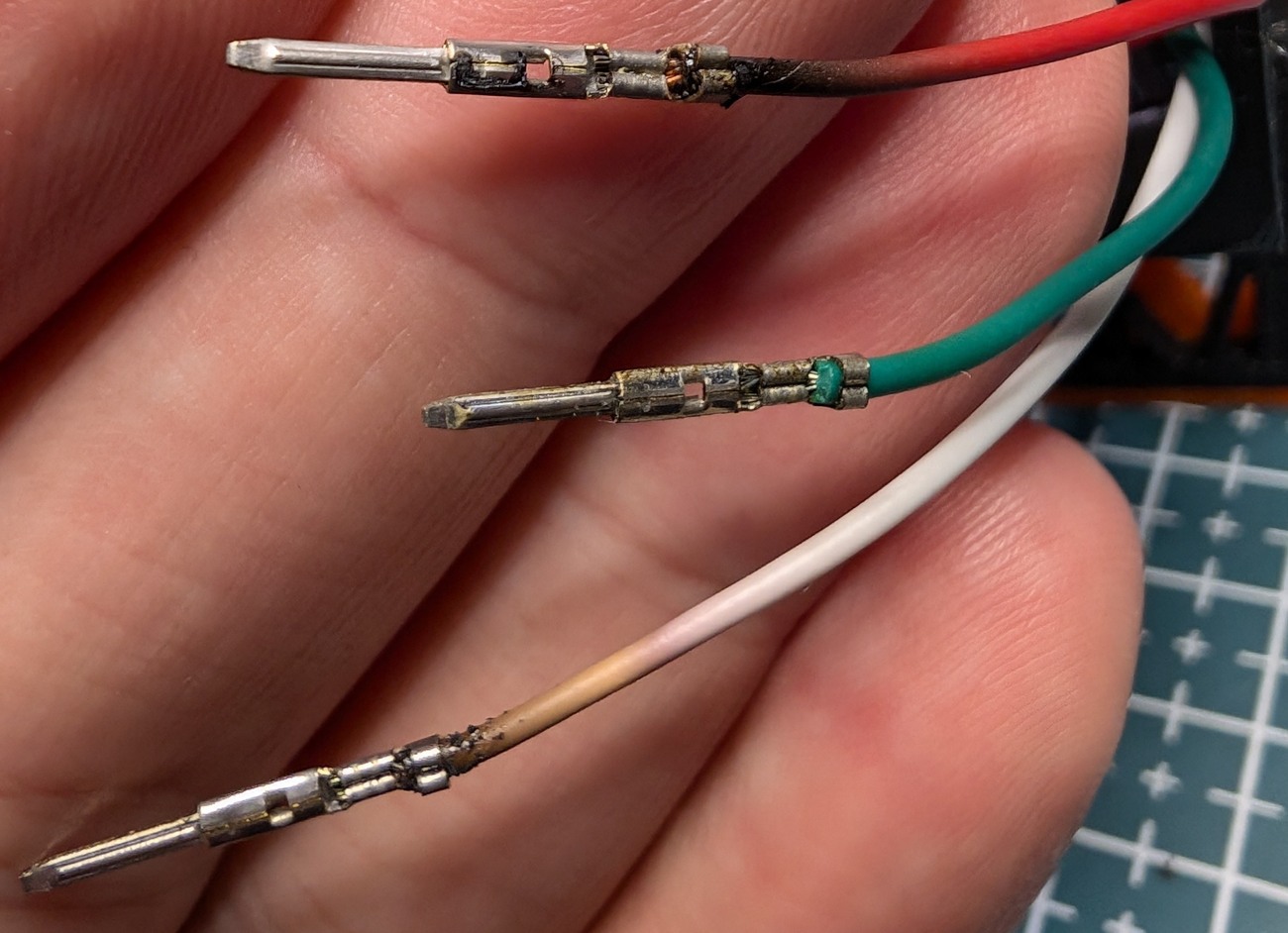
(not on purpose. The JST connector housing had turned to plastic dust from constant heat exposure when I went to do some maintenance on another LED strip I have. I knew these wires were too thin to supply power, but evidently I put things back together incorrectly at some point)
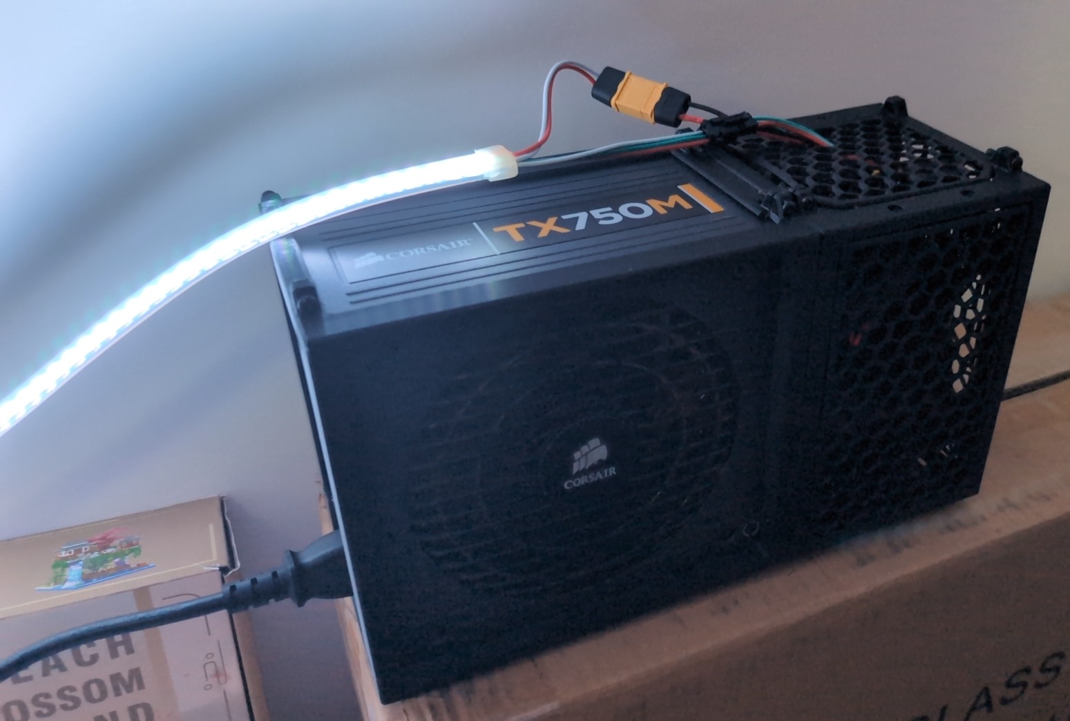
But here it is with a XT60 connector (overkill but pretty nice to use, would recommend):
TODO
- Faster 3D model design (somehow?)
- 12v > 5v?
- Check current ratings before starting
- Don't use a breakout
- Plan for a physical interface from the beginning
-
and actually are cheaper too? WS2811 2x5m (still 144 LED/m) for $56 🤔 ↩︎